1.3 KiB
1.3 KiB
STM Original Electronics
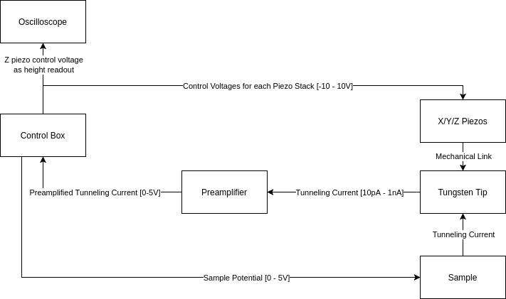
This directory contains the documentation of the original control electronics of the STM. We did some modifications which are detailed below.
Overview
The Control Box schematic can be found in STM_Main_neu_Schaltplan_3.pdf.
The Preamplifier schematic is STM_Vorverst_neu_2.pdf.
Modifications
- Preamplifier
- [2025-06-14] Added a 1nF capacitor parallel to
R10to mitigate 12kHz oscillation and stabilize the amplifier.
- [2025-06-14] Added a 1nF capacitor parallel to
- Control Box
- [2025-06-14] Disconnected
R36fromR1/C1and instead connected it to -15V through a separate 10k resistor. This inverts the setpoint voltage, which was necessary to make the differentiator actually calculate an error difference. Previously, it was summing the setpoint and control variable... - [2025-06-14] Cut out
R8, the resistor parallel to the capacitor of the integrator (I-controller). This resistor was preventing the integrator from stably integrating at very low frequencies. - [2025-06-15] Added a 1µF capacitor parallel to
C7. This mitigates 1.47 kHz oscillation when the amplifier gain is high.
- [2025-06-14] Disconnected
